Single Stage to orbit rocket simulator

Project:
1. main.cpp (Entry Point)
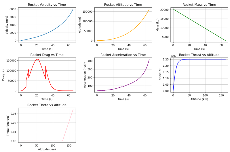
I did this project for Georgia Tech’s AE 6450 (Rocket Propulsion). The brief was simple and fun: build a single-stage-to-orbit concept by hitting a fixed total ΔV and a fixed liftoff thrust-to-weight (T/W) and let everything else be design freedom. I locked ΔV at 8,000 m/s and T/W at 5, then used my own modeling choices (engine cycle, propellants, chamber pressure, nozzle expansion, gravity-turn schedule, etc.) to make an SSTO-style ascent close. I also sized a lightweight electric “follow-on” concept to show mission closure, but the emphasis of the work—and of this write-up—is the first-stage chemical engine and its hardware.


Cycle & propellants: Why LOX/CH₄ and a gas-generator.
I chose LOX/CH₄ for clean combustion, good performance, and practical handling. To keep the scope realistic for a class project, I went with an open gas-generator (GG) cycle instead of staged combustion: far fewer integration headaches, no hot-oxygen preburner, and still plenty of shaft power for the pumps.
Thermal management: Regenerative cooling choice.
For regen I ran methane through the cooling channels (not oxygen) to avoid GOX formation and reactivity in hot passages. That choice pushes the fuel pump head higher, but it’s a good trade for materials safety.
Nozzle shape: How I generated the contour.
I first wrote a 2D method-of-characteristics (MOC) contour tool to learn the workflow, then switched to a validated axisymmetric MOC solver to get physically sized hardware. The axisymmetric solution resulted in an exit area that matched with my hand-calculations within a few centimeters, and I used that contour for the final engine CAD.
Turbomachinery: How I sized the pumps and turbine.
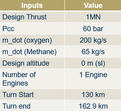
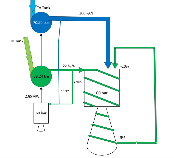
I targeted Pc ≈ 60 bar and carried empirical losses (≈20% injector, ≈15% cooling) to set pump discharge pressures. With a 3 bar inlet assumption, the results were about 88.24 bar (CH₄) and 70.59 bar (LOX) at the pump exits. I then computed pump heads, speeds, diameters, and MW-level powers from the course correlations; those powers set the turbine power. With a very fuel-rich GG (ϕ≈10), the turbine inlet temperature sits around 1039 K and the required turbine mass flow comes out near 2.44 kg/s.
The creation of the CAD files on the left was made possible thanks to the help of the Advanced Design Technology team who kindly allowed me to use their TURBOdesign software. It was user friendly and easy to use. I'm really grateful to the team. Thanks to the CAD files, I was able to print a scaled version of the Engine CAD, which earned me extra points during the presentation! Click the button on the left for a more detailed presentation on my use of TURBOdesign.
CAD linkage: Turning numbers into hardware.
Once I had the pump/turbine numbers, I generated blade profiles in ADT and integrated them into the power-pack CAD with the MOC nozzle.
Combustion properties: How I used Cantera.
I used Cantera in Python to compute chamber-gas properties at cryogenic inlet temperatures (∼110 K CH₄, 90 K O₂). From the chosen mass-flow split I got equivalence ratio, T₀, cp, R, and γ, which fed the throat sizing and nozzle performance calculations. For simplicity, I held these properties constant through the nozzle.
Aerodynamics & reference area: Drag and planform model.
For drag I used the standard D = ½ ρ v² Cᴅ A with a Mach-bucket Cᴅ approximation (0.2 subsonic, 0.5 transonic, 0.3 supersonic, 0.6 hypersonic). The rocket cross-sectional area ties directly to the engine count and exit areas (tight-packed layout for multi-engine options), so propulsion and aerodynamics stay consistent.
Mass & T/W bookkeeping: Tying it to the ascent target.
At liftoff I compute thrust from the sea-level equivalent exhaust velocity and total mass flow, then back out wet mass from T/W = 5. The ascent loop runs until the 8,000 m/s target is reached (or prop is essentially exhausted)

Engine Summary